Issue 1) What the heck happened? It is not the fisheye effect. My front panel LEDs appear to retreat into the case toward the center; however, it looks almost flush on the sides. Looking back at the instructions, I think I may have missed the step where I was supposed to put one of those plastic spacers in between the front panel and PCB, to prevent "PCB sagging," but I don’t 100% remember. Also, there are a couple of solder joints that are not making a good connection to the front panel PCB, so the "INTE" LED and "A8" LED have to be jiggled to stay on. I think I fixed one of the LEDs already, back in 2015. I believe it was the "D7" LED.
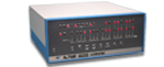
- Here is the strange shifting effect of the LEDs, the second image is probably the source of this bend.
- As we can see here, there is a noticeable PCB bend in the middle, so using the plastic spacers would have had to be a necessity.
I will be fixing the LED issues soon. Overall, it might just be easier to take out the front panel, desolder all of the LEDs, buy a whole 36-piece LED set, and redo it properly. That said, I don’t see why I can’t just skip that spacer step and just mount the LEDs loosely until the whole front panel is mounted in that L-Bracket. After all that, I could just push them flush into the front panel and solder each one as I go (hopefully the LEDs flange out far enough to catch). Reduced warping tolerances would be an absolute worst-case scenario for this method. I would like to hear everyone’s input, especially our leader, the good man himself, as well. Feel free, to be honest, I can take criticism. Also, if you have any advice, it would be most appreciated. Overall, my excuse for the butchered soldering job was lack of experience. I will add that I redid most of the joints in 2015, so they look a lot better now than when these were taken.
Issue 2) in 2013, my understanding of the RS232 was established to me from the physical connector rather than the protocol standard. I didn’t know that they were separate. This was one of my hardest gremlins to resolve after I finished the kit. I did not have the proper tool to wire together the RS-232 data cables and slot them into their Molex connectors—I didn’t even know there was a proper tool for them until about two years ago on a separate project for my car. I’m not quite sure if I had the wiring correct the first time I had the system set up, but I was definitely having intermittent connection problems due to my terrible “crimp” job.
- Here is my big no no. I know, it is painful. I want to redeem this and the fix by getting a whole new set.
I don’t know why I thought this was a good idea at the time, but I decided it was better to solder all the male pins straight to the wires (bypassing the Molex connectors) going to the DB-25 connector on the board. In hindsight, alligator clips would have been just fine. Well, this did two things: it fixed the intermittent connection problem to the terminal emulator, but it made those male Molex pins thicker, so if I wanted to go back to the female connector, it would be next to impossible to slip back on. This was the case when I decided to reverse my mistake in 2015. That said, I will be replacing the connectors Male and Female, and possibly purchasing some replacement DB-25 connectors (I think I wired the port up like a Null Modem, when it should have been 1 to 1.
As an improvement to the overall experience, and to slim the wire clutter down, I was thinking of using a Raspberry Pi Zero W with an RS-232 Serial Port. That way, I could SSH into the Pi, then MiniCom into "/dev/ttys0," thus a wireless console. I will keep the back connector and just run one of those flat ribbon cables out the back to make it easier to switch between the Pi and a traditional console. I will make use of that "AUX" switch jumper for the ATX mod and use it to power the Pi off. I can probably write a quick script with Python.