I've always wanted to make an RS-232 adapter for the Teletype that simply plugged into P2 (one of the eight molex connectors on the back of the UCC). No other wiring is required. Power is available on the connector (48 vac) and the current loop signals are present on P2 as well as on the terminal strip.
Mike
RS-232 to current loop (again)
28 posts
• Page 2 of 3 • 1, 2, 3
Re: RS-232 to current loop (again)
![]() by AltairClone » August 9th, 2017, 4:49 pm
by AltairClone » August 9th, 2017, 4:49 pm
- AltairClone
- Site Admin
- Posts: 641
- Joined: April 5th, 2013, 10:55 am
Re: RS-232 to current loop (again)
![]() by toml_12953 » August 10th, 2017, 2:53 am
by toml_12953 » August 10th, 2017, 2:53 am
AltairClone wrote:I've always wanted to make an RS-232 adapter for the Teletype that simply plugged into P2 (one of the eight molex connectors on the back of the UCC). No other wiring is required. Power is available on the connector (48 vac) and the current loop signals are present on P2 as well as on the terminal strip.
Mike
So go ahead and make one! If you plan on actually doing it, please add me to your list of buyers and notify us when it's ready to ship. Thanks!
- toml_12953
- Posts: 304
- Joined: June 7th, 2013, 12:54 pm
Re: RS-232 to current loop (again)
![]() by AltairClone » September 3rd, 2017, 10:16 am
by AltairClone » September 3rd, 2017, 10:16 am
Has anyone ever seen an ASR33 with a UCC-6 with anything plugged into P1 or P2?
Mike
Mike
- AltairClone
- Site Admin
- Posts: 641
- Joined: April 5th, 2013, 10:55 am
Re: RS-232 to current loop (again)
![]() by toml_12953 » September 3rd, 2017, 3:19 pm
by toml_12953 » September 3rd, 2017, 3:19 pm
AltairClone wrote:I've always wanted to make an RS-232 adapter for the Teletype that simply plugged into P2 (one of the eight molex connectors on the back of the UCC). No other wiring is required. Power is available on the connector (48 vac) and the current loop signals are present on P2 as well as on the terminal strip.
Mike
So what's stopping you? :) I'd buy one to get rid of the tricky B&B interface I have now. It works but hangs down the back and can be a pain to keep connections.
- toml_12953
- Posts: 304
- Joined: June 7th, 2013, 12:54 pm
Re: RS-232 to current loop (again)
![]() by mail@gabrielegan.com » September 9th, 2017, 3:57 am
by mail@gabrielegan.com » September 9th, 2017, 3:57 am
I've bought another RS232-current loop adaptor to try to connect my ASR33 Teletype to my Altair clone after the old adaptor stopped working. This one has 5 terminals marked TB1 thru TB5 and for active-transmit and active-receive the connections seem to be:
TB1 TX I+ Out / V+
TB2 nothing
TB3 RX I+ Out / V+
TB4 nothing
TB5 TX/RX I- In / V-
My problem is figuring out which of the four wires from the ASR33 to connect to which of those 5 terminals. On my old RS232-current loop adaptor, the following connections worked:
TTY red wire to adaptor terminal K that is labelled R-
TTY white wire to adaptor terminal G that is labelled T-
TTY blue wire to adaptor terminal J that is labelled GND
TTY black wire to adaptor terminal M that is labelled GND
The mytery is that, using this old mapping that worked, the Teletype seems not to have wires for T+ or T+ at all: the current seems to flow between T- and GND and between R- and GND. Can anyone figure out how my four Teletype wires map onto the five terminals on the new adaptor? Also, I presume I should set the new adaptor to 20ma, Active Transmit, Active Receive, and DCE (not DTE), right? I supply current to the adaptor using a USB cable that came with it. On the Altair side of the adaptor the connection is a DB-25 serial port female socket and since the Altair serial ports are also female I use a 25-pin male-to-male gender-changer to plug the adaptor into the Altair. Any of that sound wrong?
The instructions for the new adaptor are here:
http://gabrielegan.com/scratch/new-RS232-current-loop-adaptor.tif
Anyone's thoughts on what I'm doing wrong would be much appreciated.
Regards
Gabriel Egan
- mail@gabrielegan.com
- Posts: 104
- Joined: October 11th, 2014, 8:12 am
Re: RS-232 to current loop (again)
![]() by AltairClone » September 9th, 2017, 1:08 pm
by AltairClone » September 9th, 2017, 1:08 pm
I'd set the switches to 20, DTE, ACT, ACT
Adapter pin 1 to Teletype terminal strip pin 7 (data to Teletype+)
Adapter pin 5 to Teletype terminal strip pin 6 (data to Teletype-)
Adapter pin 3 to Teletype terminal strip pin 4 (data from Teletype)
Adapter pin 5 to Teletype terminal strip pin 3 (data from Teletype)
Mike
Adapter pin 1 to Teletype terminal strip pin 7 (data to Teletype+)
Adapter pin 5 to Teletype terminal strip pin 6 (data to Teletype-)
Adapter pin 3 to Teletype terminal strip pin 4 (data from Teletype)
Adapter pin 5 to Teletype terminal strip pin 3 (data from Teletype)
Mike
- AltairClone
- Site Admin
- Posts: 641
- Joined: April 5th, 2013, 10:55 am
Re: RS-232 to current loop (again)
![]() by mail@gabrielegan.com » September 20th, 2017, 2:50 am
by mail@gabrielegan.com » September 20th, 2017, 2:50 am
Thanks, Mike
With those connections the Teletype receives data from the Altair, but cannot send data to it. The serial port is definitely good: my other Teletype (which came with a converter already wired in, thank heavens) works fine on the same serial port. To double-check which coloured wire in the lead from the Teletype is connected to which terminal on the Teletype terminal strip, I opened the Teletype and used a multimeter set to 'resistance' as a circuit tester. Here is what I found:
Teletype terminal strip terminal 4 to Black wire: No resistance
Teletype terminal strip terminal 3 to Red wire: No resistance
Teletype terminal strip terminal 4 to Red wire: No resistance
Teletype terminal strip terminal 6 to White wire: No resistance
Teletype terminal strip terminal 7 to White wire: No resistance
Teletype terminal strip terminal 6 to Blue wire: No resistance
Teletype terminal strip terminal 7 to Blue wire: No resistance
The Teletype terminals strip terminals that each wire goes to are:
Teletype terminal strip terminal 4 has Black wire connected to it
Teletype terminal strip terminal 3 has Red wire connected to it
Teletype terminal strip terminal 7 has White wire connected to it
Teletype terminal strip terminal 6 has Blue wire connected to it
On the basis of the above, I interpreted your instructions as:
Adapter pin 1 to Teletype White wire
Adapter pin 5 to Teletype Blue wire
Adapter pin 3 to Teletype Black wire
Adapter pin 5 to Teletype Red wire
Any thoughts on why I'm only get data to the Teletype and not from it?
Regards
Gabriel
- mail@gabrielegan.com
- Posts: 104
- Joined: October 11th, 2014, 8:12 am
Re: RS-232 to current loop (again)
![]() by AltairClone » September 20th, 2017, 12:13 pm
by AltairClone » September 20th, 2017, 12:13 pm
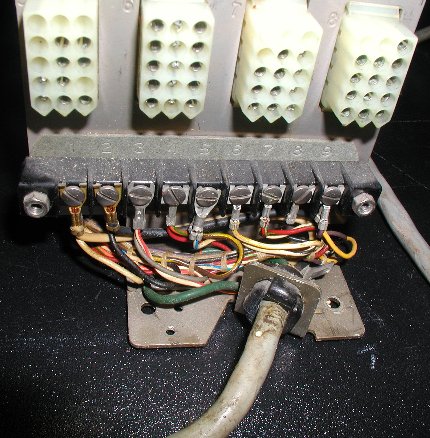
I'm very confused by the wiring colors you've listed. Most all of the wires going to the terminal strip (from within the Teletype) are bi-colored wires. I'd expect the following on 3-7. Is this a Teletype that was working previously with your other RS-232 to 20ma converter?
3 silver, white-red
4 red, orange-green
5 brown-yellow, white-blue
6 white-black, white-yellow
7 white-brown, red-green
3 silver, white-red
4 red, orange-green
5 brown-yellow, white-blue
6 white-black, white-yellow
7 white-brown, red-green
- AltairClone
- Site Admin
- Posts: 641
- Joined: April 5th, 2013, 10:55 am
Re: RS-232 to current loop (again)
![]() by mail@gabrielegan.com » September 20th, 2017, 12:28 pm
by mail@gabrielegan.com » September 20th, 2017, 12:28 pm
Dear Mike
Sorry, yes there are lots of other wires going to the terminals of the terminal strip in addition to the four single-coloured wires I identified. These other wires connect to various internal parts of the Teletype. Those four single-coloured wires I described are the ones that (inside a common sheath) run from the terminal strip to outside the Teletype to form its 'data communication' cable.
Regards
Gabriel
- mail@gabrielegan.com
- Posts: 104
- Joined: October 11th, 2014, 8:12 am
Re: RS-232 to current loop (again)
![]() by AltairClone » September 20th, 2017, 2:10 pm
by AltairClone » September 20th, 2017, 2:10 pm
Ok, that makes more sense. Didn't realize you already had a data cable connected to the terminal block. Your wiring to the Teletype and adapter sounds correct. What are you connecting to the adapter? The Altair Clone or a PC? If connected to the Altair Clone and using a serial port configured as a 2SIO port, be sure that handshake option 1 is selected (CTS, RTS Always Asserted). This could prevent reception if CTS handshaking is on.
Mike
Mike
- AltairClone
- Site Admin
- Posts: 641
- Joined: April 5th, 2013, 10:55 am
28 posts
• Page 2 of 3 • 1, 2, 3
Who is online
Users browsing this forum: No registered users and 2 guests